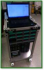
The laboratory is equipped in three 8-channel MACCOR® battery cyclers build up on portable carts with APC Smart-UPS power supplies that allow cycler transport around the ring without disturbing running battery cells. The carts also contain basic supplies such as alligator cables, banana cables, Velcro, cable ties, allen wrenches and Fluke Multimeter. Coin cells holders and AMPIX cells and holders are available by additional request. While all of our MACCOR® cyclers can be used for routine galvanostatic, PITT, GITT measurements, each cycler has unique configuration and capability. You can check common and unique specifications bellow.
Note: Please plan ahead. Request the equipment as soon as you know your beamtime dates
MACCOR 4300 cycler 1 MACCOR 4300 cycler 2 MACCOR 4300 cycler 3
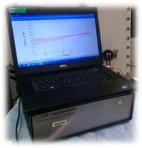
CHInstruments 660e Potentiostat
Request equipment needed
Our laboratory provides services based on "first come first served" basis – book as soon as you know about your beam time.
Portable 8-channel MACCOR® battery cyclers (model 4300)
Standard system that provides the highest level of accuracy and time resolution. The simplified short guide for our users answering most common questions can be find here .
- Each test channel is controlled independently of the other channels in the system.
- Step types include: Charge (Source Current), Discharge (Sink Current), Rest (Wait), Voltage Scan, Pulse – 10 ms standard.
- Steps can be user programmed to operate in modes of constant (fixed) current, power, voltage, or resistance. Each test step can have up to 16 different end conditions.
- Tests can branch to any step in the test based on the step end criteria met.
- Step end conditions include but are not limited to: measured values (voltage, current, time, etc.), integrated values (energy, capacity, half cycle data), and calculated values (ΔV/δt, ΔT/δt, first and second derivatives).
- Four levels of loop nesting are available in each test.
- Test procedures can be called as a subroutine in another test yielding virtually limitless step lengths.
- Similarly rated test channels can be combined in parallel in groups of 2, 4, or 8 to yield higher current rated channels when needed.

Cyclers specifications:
Number of Channels 8
Current Control Range 300 ηA to 5 A
- Range 1 150 μA Full Scale ±30 ηA
- Range 2 5 mA Full Scale ± 1 μA
- Range 3 150 mA Full Scale ±30 μA
- Range 4 5 A Full Scale ± 1 mA
Modes of Operation
- Constant Current
- Constant Power
- Constant Resistance
- Constant Voltage
- Voltage Scan (Cyclic Voltametry)
- Fixed 1kHz AC Impedance Measurement
Time
- Minimum Step Time 10 mS
- Control, Measurement, and Adjustment - every 10 mS
Interface Cables
3m in length 4-wire interface cables, terminated with mini banana connectors(alligator and standard banana (4) terminated cables available by request)
Unique Cycler Specifications
Auxiliary voltage inputs
MACCOR 4300 cycler 1 - is equipped in sixteen auxiliary voltage inputs that are assignable to any test channel through software. The voltage inputs are high impedance fully isolated and can be specified with various ranges such as: ±5 volts, ±10 volts, etc). Any combination of voltage inputs can be assigned to a test channel, and data measured by these inputs becomes part of the data record for the test channel assigned. Voltages measured by these inputs can control operation of the test channel assigned, display real time values, or plotted either as a single input or overlay all the inputs associated with the test.
MACCOR 4300 cycler 2 & MACCOR 4300 cycler 3 - no auxiliary voltage inputs
Voltage range
MACCOR 4300 cycler 1 & MACCOR 4300 cycler 2 : from 0V to +10 Volts ±2 mV
MACCOR 4300 cycler 3 : from -5V to +10 Volts ±3 mV
Single Channel CHInstruments® 660e Potentiostat
General purpose electrochemical measurements instrument. It offers a very wide dynamic range of experimental time scales. The potentiostat / galvanostat uses a 4-electrode configuration, allowing it to be used for liquid/liquid interface measurements, and eliminating the effect of the contact resistance of connectors and relays for high current measurements. The data acquisition systems also allow an external input signal (such as spectroscopic) to be recorded simultaneously during an electrochemical measurement. The instrument is capable of a wide variety of electrochemical techniques, and is available with integrated simulation and fitting software functions for both impedance and cyclic voltammetry. These features provide powerful tools for both electrochemical mechanistic studies and trace analysis. Check availability: CHInstruments 660e Potentiostat

Technical Specifications:
Available Techniques
- Cyclic Voltammetry (CV)
- Linear Sweep Voltammetry (LSV)
- Staircase Voltammetry (SCV)
- Tafel Plot (TAFEL)
- Chronoamperometry (CA)
- Chronocoulometry (CC)
- Differential Pulse Voltammetry (DPV)
- Normal Pulse Voltammetry
- Differential Normal Pulse Voltammetry (DNPV), (NPV)
- Square Wave Voltammetry (SWV)
- AC Voltammetry (ACV)
- 2nd Harmonic AC Voltammetry (SHACV)
- Fourier Transform AC Voltammetry (FTACV)
- Amperometric i-t Curve (i-t)
- Differential Pulse Amperometry (DPA)
- Double Differential Pulse Amperometry (DDPA)
- Triple Pulse Amperometry (TPA)
- Integrated Pulse Amperometric Detection (IPAD)
- Bulk Electrolysis with Coulometry (BE)
- Hydrodynamic ModulationSweep-Step Functions (SSF)
- Multi-Potential Steps (STEP)AC
- Impedance (IMP)Impedance - Time (IMPT)
- Impedance - Potential (IMPE)
- Chronopotentiometry (CP)
- Voltammetry (HMV)
- Chronopotentiometry with Current Ramp (CPCR)
- Multi-Current Steps (ISTEP)
- Potentiometric Stripping Analysis (PSA)
- Electrochemical Noise Measurement (ECN)
- Open Circuit Potential - Time (OCPT)
- Galvanostat
- RDE control (0-10V output)
- Full version of CV simulation and fitting program
- Impedance simulation and fitting program
- iR Compensation
- External Potential Input
Experimental Parameters
- CV and LSV scan rate: 0.000001 to 10,000 V/s
- Potential increment during scan: 0.1 mV @ 1,000 V/s
- CA and CC pulse width: 0.0001 to 1000 sec
- CA and CC minimum sample interval: 1 μs
- True integrator for CC
- DPV and NPV pulse width: 0.001 to 10 sec
- SWV frequency: 1 Hz to 100 kHz
- i-t sample interval: minimum 1 μs
- ACV frequency: 0.1 Hz to 10 kHz
- SHACV frequency: 0.1 Hz to 5 kHz
- FTACV frequency: 0.1 Hz to 50 Hz, simultaneously acquire 1st, 2nd, 3rd, 4th, 5th, and 6th harmonics ACV data
- IMP frequency: 0.00001 Hz to 1 MHz
- IMP amplitude: 0.00001 V to 0.7 V rms
Other Features
- Automatic and manual iR compensation
- Current measurement bias: full range with 16-bit resolution, 0.003% accuracy
- External potential input
- Potential and current analog output
- Programmable potential filter cutoff: 1.5 MHz, 150 KHz, 15 KHz, 1.5 KHz, 150 Hz, 15 Hz, 1.5 Hz, 0.15 Hz
- Programmable signal filter cutoff: 1.5 MHz, 150 KHz, 15 KHz, 1.5 KHz, 150 Hz, 15 Hz, 1.5 Hz, 0.15 Hz
- RDE control output (selected models): 0-10 V (corresponding to 0-10000 rpm), 16-bit, 0.003% accuracy
- Digital input/output lines programmable through macro command
- CV simulation and fitting program, user-defined mechanisms
- Impedance simulation and fitting program
Potentiostat
- Zero resistance ammeter
- 2- or 3- or 4-electrode configuration
- Floating (isolated from earth) or earth ground
- Maximum potential: ±10 V
- Maximum current: ±250 mA continuous, ±350 mA peak
- Compliance Voltage: ±13 V
- Potentiostat rise time: < 1 μs, 0.8 μs typical
- Applied potential ranges (volts): ±0.01, ±0.05, ±0.1, ±0.65, ±3.276, ±6.553, ±10
- Applied potential resolution: 0.0015% of potential range
- Applied potential accuracy: ±1 mV, ±0.01% of scale
- Applied potential noise: < 10 μV rms
- Measured current range: ±10 pA to ±0.25 A in 12 ranges
- Measured current resolution: 0.0015% of current range, minimum 0.3 fA
- Current measurement accuracy: 0.2% if current range >=1e-6 A/V, 1% otherwise
- Input bias current: < 20 pA
Galvanostat
- Galvanostat applied current range: 3 nA - 250 mA
- Applied current accuracy: 20 pA ±0.2% if > 3e-7A, ±1% otherwise
- Applied current resolution: 0.03% of applied current range
- Measured potential range (volts): ±0.025, ±0.1, ±0.25, ±1, ±2.5, ±10
- Measured potential resolution: 0.0015% of measured range
Electrometer
- Reference electrode input impedance: 1x10¹² ohm
- Reference electrode input bandwidth:10 MHz
- Reference electrode input bias current: <= 10 pA @ 25°C
Waveform Generation and Data Acquisition
- Fast waveform update: 10 MHz @ 16-bit
- Fast data acquisition: dual channel 16-bit ADC, 1,000,000 samples/sec simultaneously
- External signal recording channel at maximum 1 MHz sampling rate

