


MacTest - Battery Test System Initializing Software
The MacTest software provides necessary functions and features to program tests, control test, record test data and process the test data locally or remotely. Look for Maccor icon on the desktop
- Double click on MACTEST icon on the desktop
- On the panel choose Intermediate View – This screen allows you to start test and see the status of all channels
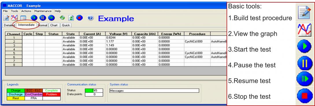
All of the pictogram icons are single-click shortcuts to some of the most used items available in the Tool Bar drop-down menus. There are more controls available in the drop down menus than there are Icons
Basic functions guides:
- Initializing Software
- Building the test procedure
- Starting the test procedure
- Viewing the data
- Exporting data
- Calculating current for desired rate
Basic Functions Vocabulary:
Charge - The operator can enter the rate of charge in the Value box for the Mode. The Mode will determine the type of the Charge step this will be (Current, Voltage ,Power or Resistance). For Current, the input entry will be in Amps.
Discharge -The operator can enter the rate of discharge in the Value box for the Mode. The Mode will determine the type of the Discharge step this will be (Current, Voltage, Power or Resistance).
Rest - places the channel in an effective open circuit condition (turns Current off)
Pause - suspends channel testing. The operator must manually force next step of the the test by clicking the Resume button. The test will advance to the step that follow the Pause step.
Advance Cycle - Changes cycle numbering in the intermediate screen and within the data. It simplifies data handling and allows finding data from the specific cycle easily.
End - will end the test and/or permanently terminate the collection of data in the data file created on the test computer. The last step of all test procedures must be an End step.
ExtChg - will charge the device under test, using Current from an externally supplied power source. The tester does not control Current during this step, but data collection and end-condition checking still takes place. The operator can use this Type only on test channels having the External Charge Controller hardware option.
ExtDis - will discharge the device under test through an externally-supplied load control device. The tester does not control Current, but data collection and end-condition checking still takes place. The operator can use this Type only on test channels having the External Load Controller hardware option.
Do begins a loop, which works in conjunction with the Loop. Each Do command must have a matching Loop command in the test procedure. The Do/Loop feature allows the operator to repeat steps in a procedure by placing them between the Do and the Loop. The operator specifies the number of loops the procedure will repeat in the Loop command. Do1 cannot be repeated until after a Loop1.
Loop - causes the test to jump back to the step following the previous Do step unless one of the End Conditions is already satisfied. The counter for the number of loops is decremented by one. Each Loop must have a matching Do preceding it. Do/Loops must have a Loop Count specified in the End Type – Op – Value fields. This Do/Loop combination is used to execute a block of repeated steps.
The maximum loop count is 32,000.
Scan - utilizes the Voltage Mode of operation, and the operator enters a scan rate in V/s. The minimum entry is 10uV/second, and the maximum entry is 1V/second. The system will maintain that slope, either negative or positive, until an End Condition is satisfied. The Current will automatically be adjusted to maintain the entered scan value. The starting Voltage for the step will be the device’s actual Voltage when it enters this step. The channel will automatically change from charge to discharge within a Scan step as needed to maintain the commanded scan slope.
It is easy to program in a voltage rate that is too high, and the resultant current may exceed the channel’s capacity or the device’s current rating. You should not put in a current limit because it can change the slope, and therefore, the validity of the scan. Due to the dynamic control nature of the Voltage scan, you should never suspend a channel in a scan step.
While building a test procedure using the Scan step, clicking in the Value box will bring up a message: "If the above entry had a minus sign (-) in front, the system would perform a negative scan causing a negative slope".